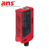
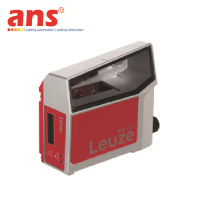
Leuze ILSER 25B/4-S12 Through-beam Photoelectric Sensor (Receiver - Genuine)
Price: Contact
Brand: Leuze
Category: Cảm biến công nghiệp
Supplier: AnhNghiSon
Origin: Germany
LEUZE ILSER 25B/4-S12 THROUGH-BEAM PHOTOELECTRIC SENSOR RECEIVER (PART NUMBER: 50108487)
DEEP PRODUCT OVERVIEW & SYSTEM ARCHITECTURE
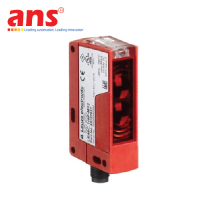
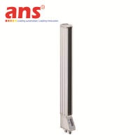
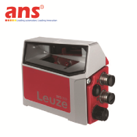
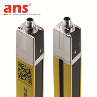
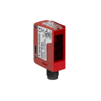
The Leuze ILSER 25B/4-S12 (Order Part Number: 50108487) is a premium-tier industrial through-beam photoelectric sensor component belonging to the high-performance 25B Series ecosystem engineered by the global automation leader Leuze electronic (Germany). This advanced device functions exclusively as the light receiver (Receiver - RX) within a through-beam photoelectric sensor configuration. Due to the baseline technical architecture of the direct through-beam principle, this device is classified as a combination product and cannot function as a standalone, isolated unit. To complete a functional automated measurement loop, the operator must align and configure this receiver alongside a compatible light transmitter (Transmitter - TX) from the matching 25B Series (such as the standard LSSR 25B line) mounted directly opposite. Driven by its ultra-wide scanning range and responsive digital evaluation microcircuitry, the ILSER 25B/4-S12 delivers uncompromising tracking integrity across heavy-duty industrial conveyor tracks, smart warehouse logistics cells, and large-scale manufacturing sorting arrays.
CRITICAL PRODUCT LIFECYCLE NOTE & RECOMMENDED UPGRADE PATH
Please note that the ILSER 25B/4-S12 (50108487) model has been officially designated as Discontinued by Leuze electronic to make way for modernized and optimized sensing platforms. To maintain factory line continuity and eliminate costly production bottlenecks when an old unit fails, Leuze has designated the next-generation LE25C/4W-M12 (Part Number: 50139703) as the exact functional drop-in replacement equivalent, matching both operational performance and core electrical pinning. When executing system maintenance or overhaul procedures, controls engineers must pay careful attention to optical cross-generation compatibility. Upgrading an old receiver to the new 25C Series requires a thorough check of the pre-installed 25B transmitter's compatibility. Automation experts highly recommend replacing the hardware synchronously as a matched pair (both a new transmitter and a new receiver) to lock down absolute millimetric precision, optimize system response frequency, and ensure maximum long-term system durability.
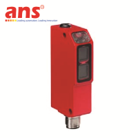
DIRECT THROUGH-BEAM PRINCIPLE & EMBEDDED SMART WARNING OUTPUT TECHNOLOGY
The sensor system operates strictly on the direct through-beam principle, establishing a linear optical path between the transmitter and the receiver arrays. The opposite transmitter continuously projects a visible red light beam across the physical gap aimed directly into the receiver lens window of the ILSER 25B/4-S12. The precise second any moving target cuts this optical path, light transmission is blocked, and the internal microcircuitry instantly registers the beam interruption, triggering its output states at a powerful industrial switching frequency of 500 Hz—perfectly tuned for high-velocity packaging and processing tracks.
The core technical advantage of the ILSER 25B/4-S12 lies in its dual independent PNP transistor digital output channels, driving separate system logics:
- Output 1 (Primary Channel): Operates on Light Switching logic, meaning the digital output state remains continuously closed (ON) when the optical beam path is unobstructed, and toggles open (OFF) the instant a passing object blocks the red light.
- Output 2 (Specialized Channel): Functions as a smart optical Warning Output. The integrated electronics continuously analyze the amplitude of incoming light energy. If the lens window undergoes progressive dust accumulation from severe shop floor environments or suffers a minor technical alignment shift that degrades light transmission, the warning output triggers an early predictive alarm to the master PLC before the sensor completely fails. This allows plant maintenance teams to clean or adjust the hardware proactively during scheduled downtime, averting sudden line stoppages.
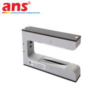
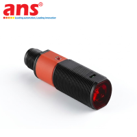
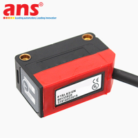
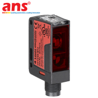
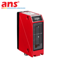
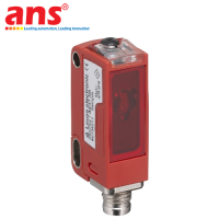
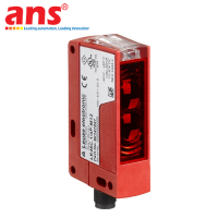
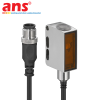
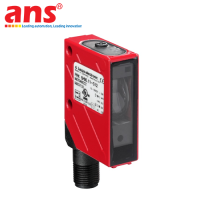
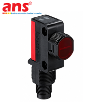
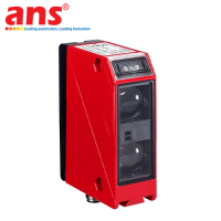
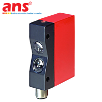
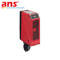
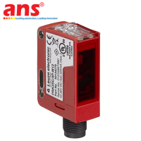
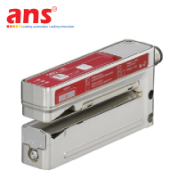
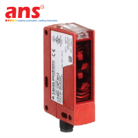
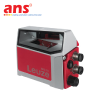
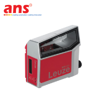
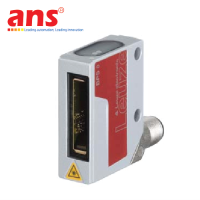
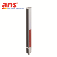
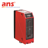
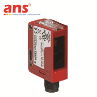
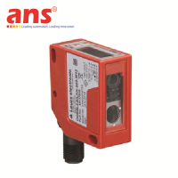
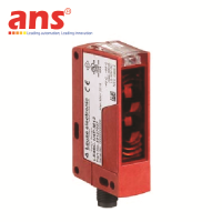
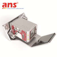
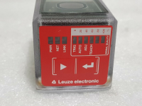
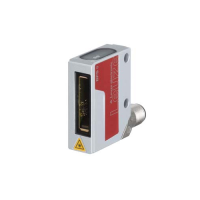
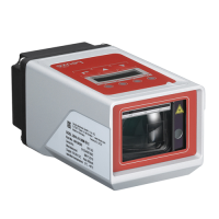
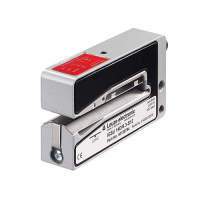
MINIMALIST CUBIC FOOTPRINT & TOUGH INDUSTRIAL SHIELDING
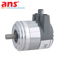
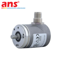
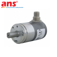
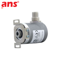
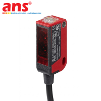
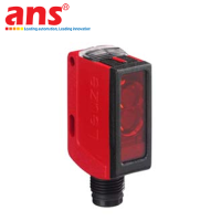
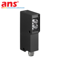
- Streamlined Rectangular Cubic Layout: Measuring an ultra-compact 15 mm × 38.9 mm × 28.7 mm, the sensor effortlessly fits into tight mechanical layout spaces, narrow recesses, or along conveyor guide frames via structural through-hole bolt fastening.
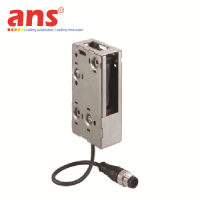
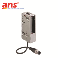
- Advanced Material Build: The enclosure is molded from high-grade PC-ABS engineering polymer alloy, delivering superior mechanical impact absorption, structural fatigue resistance, and durability under mild chemical exposure. The lens window is crafted from high-transmittance optical PMMA plastic to optimize light capture. The device comes standard with a factory-sealed industrial M12 male connector featuring a 4-pin layout with A-coded mechanical alignment (indicated by the -S12 suffix), completely shielding the interface from loose connection issues under machine vibration and eliminating field wiring complexity.
OPTICAL DATA & RECEIVER CAPACITY
- Operating Principle: Receiver (RX) component of a through-beam photoelectric sensor system
- Hardware Configuration: Combination product (Requires synchronized deployment with a compatible 25B Series transmitter)
- Tracking Light Source: Visible Red Light projected from the opposing transmitter unit
- Maximum Sensing Range Limit: Up to 24 meters (The optimal real-world tracking distance will vary dynamically based on factory floor dust concentration and humidity levels)
ELECTRICAL SPECIFICATIONS & SIGNAL OUTPUT
- Supply Voltage Type: Direct Current (DC) within standard industrial regulation rails
- System Switching Frequency: 500 Hz (Optimized for ultra-responsive unit counting and high-velocity item tracking)
- Total Digital Channels: 2 Independent Digital Transistor channels
- Transistor Output Configuration: PNP Type
- Digital Output Switching Mode Logic:
+ Output 1 (Primary): Light Switching logic (Closes circuit output state to ON when the optical beam path is clear and unobstructed)
+ Output 2 (Specialized): Smart predictive Warning Output channel (Triggers closed circuit logic when optical transmittance drops due to fine dust build-up or lens clouding)
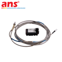
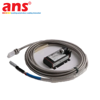
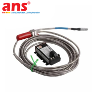
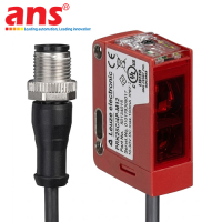
CONNECTION INTERFACE & PIN ASSIGNMENT
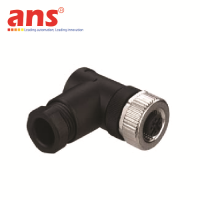
- Electrical Connection Type: Integrated M12 Standard Quick Disconnect Plug (Male Connector)
- Number of Contact Pins: 4-pin layout
- Mechanical Connector Alignment: A-coded industrial specification (Suffix indicator: -S12)
- Standard Pin Mapping Layout:
+ Pin 1: Positive Voltage Input Rail (+24VDC)
+ Pin 3: Negative Voltage Input Rail (0V / GND)
+ Pin 4: Digital Output 1 Signal Lead (PNP Light switching)
+ Pin 2: Digital Output 2 Signal Lead (PNP Warning output)
* Interconnect Note: Controls personnel must cross-examine the official manufacturer wiring diagram of the active field infrastructure prior to physical commissioning.
MECHANICAL PROPERTIES & MATERIAL COMPOSITION
- Physical Enclosure Style: Compact rectangular block profile (CUBIC form factor)
- Physical Housing Dimensions (W × H × L): 15 mm × 38.9 mm × 28.7 mm
- Enclosure Substrate Material: Rigid high-impact-resistant PC-ABS engineering plastic (Signature Leuze Red)
- Lens Window Window Material: Optical grade, high-transmittance PMMA plastic polymer
- Fixing Assembly Method: Secure through-hole structural bolt mounting directly through the sensor casing
PRODUCT LIFECYCLE STATUS & UPGRADE DISPATCH
- Commercial Status: Officially Discontinued by Leuze electronic
- Recommended Next-Generation Replacement Model: LE25C/4W-M12 (Order Part Number: 50139703) from the upgraded Leuze 25C Series product lineup.