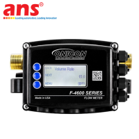
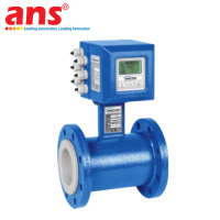
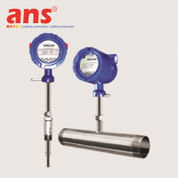
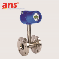
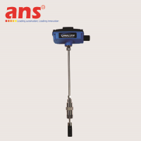
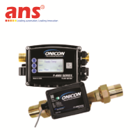
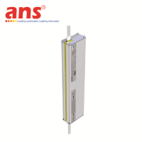
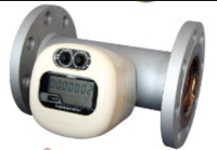
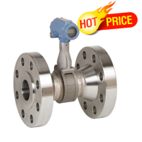
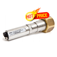
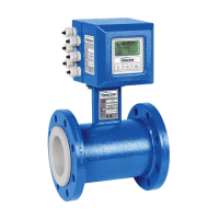
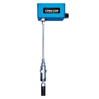
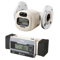
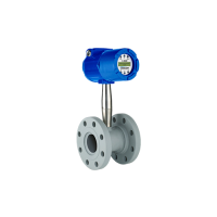
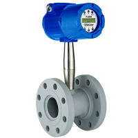
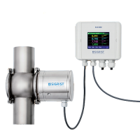
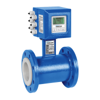
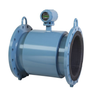
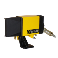
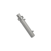
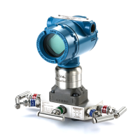
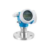
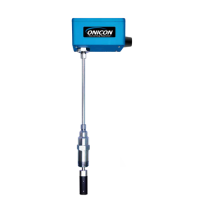
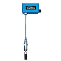
ONICON FT-4600-250-120-09 2.5 Inch (DN65) Inline Flanged Ultrasonic Flow Meter
Price: Contact
Brand: ONICON
Category: Thiết bị đo lường & Kiểm tra
Supplier: AnhNghiSon
Origin: USA
ONICON FT-4600-250-120-09
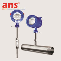
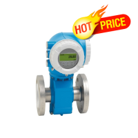
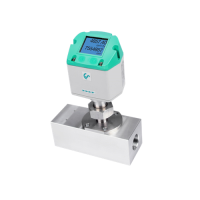
Product Overview: The ONICON FT-4600-250-120-09 Inline Flanged Ultrasonic Flow Meter is a premium process-grade heavy-duty fluid diagnostics instrument belonging to the world-renowned FT-4600 Series portfolio, engineered and manufactured 100% in the United States (USA Origin) by ONICON Incorporated. Within modern large-scale mechanical architectures of heavy commercial smart properties, hyper-scale Data Center cooling clusters, central boiler plants, and centralized high-output HVAC networks, executing rigorous, uncompromised flow telemetry along 2.5-inch (DN65) main distribution lines is foundational to automated automation control and proactive energy sub-metering.
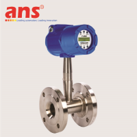
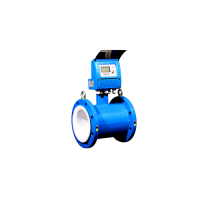
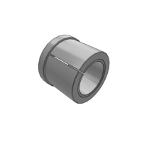
The FT-4600-250-120-09 variation profiles a completely solid-state structural design that eliminates internal mechanical moving components like turbines or rotors, avoiding mechanical wear and friction decay while preserving absolute long-term measurement fidelity over decades of plant runtimes. Crucially, according to ONICON's official ordering code criteria, for the large 2.5-inch pipe configuration (Model designation 250), the manufacturer mandates a rugged, structurally rigid ANSI Class 150 Flange mechanical interconnection scheme to manage maximum line fluid dynamic loads with total integrity.
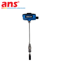
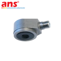
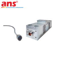
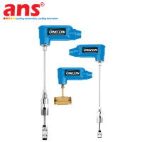
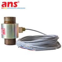
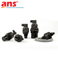
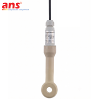
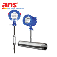
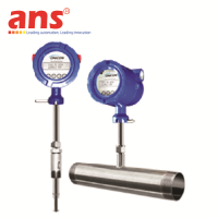
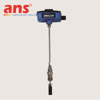
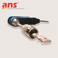
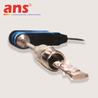
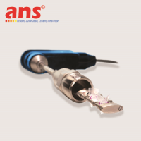
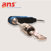
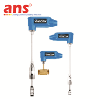
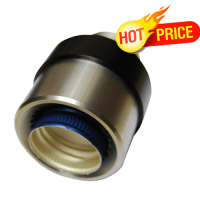
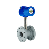
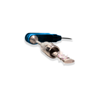
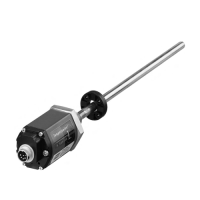
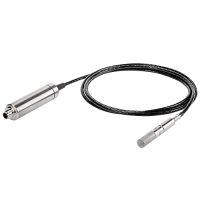
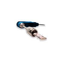
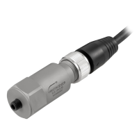
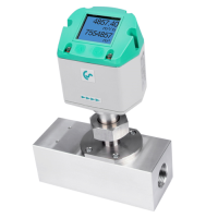
Differential Transit-Time Engineering and Wetted Sensor Technology: The underlying technological paradigm driving the FT-4600-250-120-09 variant leverages sophisticated Differential Transit-Time Ultrasonic physics. The defining hardware asset of this specific model is its native incorporation of high-precision acoustic sensors that submerge directly into the active flow loop (Wetted Ultrasonic Transducers). These high-fidelity sensing nodes are forged from an advanced 40% glass-fiber reinforced PPS (Polyphenylene Sulfide) technical composite, providing superb resilience against fluid friction and chemical cavitation breakdown.
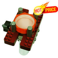
The two acoustic transducers are mounted directly opposite each other across a linear transmission line vector inside the non-corrosive Lead-Free Brass flow body. As the processed medium (water or industrial water/glycol solutions) glides through the tube, the digital telemetry engine shoots alternating high-frequency acoustic wave pulses upstream and downstream relative to the flow direction vector. The internal calculation processor analyzes the microscopic time-of-flight delta between these sonic signals to resolve continuous process velocity with exceptional data resolution. This direct-path wetted layout optimizes soundwave signal strength, delivers supreme operational consistency over multi-year runtime windows, and unlocks superior low-velocity flow tracking metrics that standard clamp-on meters fail to capture.
🛠️ FIELD INSTALLATION PROMPT & HYDRAULIC CONFIGURATION:
-
Strict Straight Pipe Run Metrics: To preserve the factory-certified accuracy threshold of plus or minus 1% of active reading, mechanical installers deploying this 2.5-inch flanged inline device must strictly maintain specified minimum straight pipe runs upstream and downstream from adjacent pipe fittings to secure a completely laminar velocity profile:
-
Downstream of a Single Elbow: Requires 0D of straight pipeline run.
-
Downstream of a Reducer or Expander: Requires 0D of straight pipeline run.
-
Downstream of a Hydronic Heating/Cooling Coil: Requires a minimum of 3D straight pipe run.
-
Downstream of a mechanical Isolation Valve: Requires a minimum of 5D straight pipe run.
-
Downstream of an automated Control Valve: Requires a minimum of 15D straight pipe run.
-
-
Critical Prohibited Installation Zones: To protect the structural wetted transducers and ensure signal integrity, do not install the meter at the direct suction line of high-capacity pumps, immediately downstream of modulating throttling valves, at top pipe apexes where air pockets assemble, or along vertical downward lines exhibiting non full-pipe states.
Hardened Hardware Topology and Telemetry Output Specifications:
-
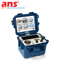
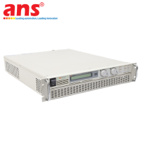
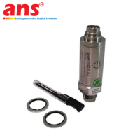
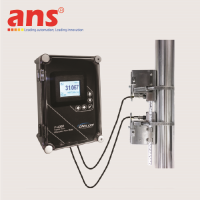
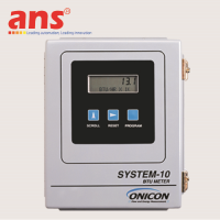
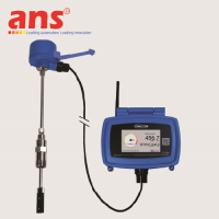
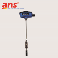
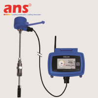
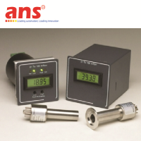
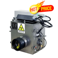
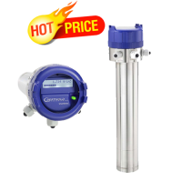
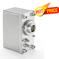
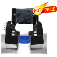
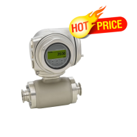
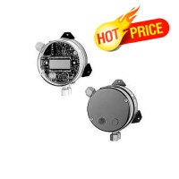
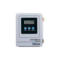
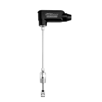
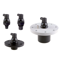
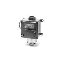
Blind Transmitter Hardened Enclosure: The FT-4600-250-120-09 hardware configuration features a blind design optimized without a local LCD panel. This layout maximizes electrical efficiency and physical ruggedness, making it perfect for high-elevation pipe racks, narrow pipe chases, or background technical crawlspaces. The internal calculation electronics are safely armored within a heavy-duty NEMA 4 housing that incorporates a premium Strain Relief Cord Grip assembly to lock wiring runs tightly against mechanical pulling and external moisture ingress.
-
Synchronized Dual Output Matrix: Features concurrent real-time data loops via an Analog channel and a discrete Pulse channel. The Analog Output is fully field-configurable, allowing automation crews to match supervisory PLC or BMS cards using standard current or voltage loops including 4-20mA, 0-10V, or 0-5V spans. The Pulse Output channel utilizes an isolated solid-state Dry Contact Pulse topology. Acting as an isolated mechanical-free electronic switch, it relays high-fidelity tracking data straight to remote totalizer units or BMS logging panels while repelling dangerous electrical line noise or high-frequency EMI generated by neighboring pump variable frequency drives (VFDs).
-
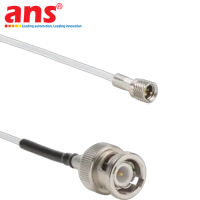
Pre-Supplied Cable Infrastructure: The meter includes a pre-wired 10 ft (approximately 3 meters) cable harness sorting utility power lines, analog loops, and pulse circuits. For extended panel runs, the manufacturer recommends deploying premium 18 to 22 AWG shielded instrumentation cabling to prevent data degeneration.
Engineering Metric |
Technical Value and Standard (Plain-Text Compliant) |
Manufacturer |
ONICON Incorporated (United States) |
Product Series |
FT-4600 Series Inline Ultrasonic Fluid Instrumentation Portfolio |
Full Manufacturing Code |
FT-4600-250-120-09 |
Measurement Principle |
Non-intrusive Non-mechanical Differential Transit Time Ultrasonic physics |
Nominal Pipe Size |
2.5 Inch / Metric Designation DN65 |
Mechanical Interface |
Heavy-duty Flanged Connection complying with ANSI Class 150 standard |
Transmitter Interface Profile |
Blind execution containing no local display panel |
System Accuracy Standard |
Plus or minus 1% of active reading across standard flow velocities (1% Reading) |
Measurement Repeatability |
Extremely stable tracking consistency, less than or equal to plus or minus 0.2% |
Overall Dynamic Range |
Spectacular Turndown Ratio locked at 500:1 |
Maximum Line Pressure |
Heavy-duty 400 psi structural pressure envelope (Approximately 27.6 bar) |
Process Temperature Boundaries |
Handles fluid media thermal windows spanning 0 to 250 degrees Fahrenheit (-18 to 121 degrees Celsius) |
Ambient Temperature Envelope |
Operates flawlessly from minus 13 to 131 degrees Fahrenheit (-25 to 55 degrees Celsius) |
Driving Utility Power |
24 VAC/DC nominal input tolerance, running across 20 to 28 VAC/DC utility bounds |
Maximum System Power Load |
Highly efficient electrical design consuming less than or equal to 5 VA Max |
Analog Output Channel |
1 x Configurable Analog Loop (Selectable via software for 4-20mA / 0-10V / 0-5V signals) |
Discrete Output Channel |
1 x Isolated Dry Contact Pulse Output (Optimized for remote totalizer / PLC logging) |
Fieldbus Communications |
Default variation comes naked with no onboard BACnet MS/TP or Modbus RTU cards |
Flow Body Metallurgy |
Forged entirely from high-grade industrial Lead-Free Brass alloy |
Transducer Structural Material |
Polyphenylene Sulfide (PPS) engineered resin reinforced with 40% glass fiber |
Enclosure Environmental Rating |
Certified to NEMA 4 industrial protective standards with an integrated Strain Relief grip |
Country of Origin |
100% Made in the United States |